MyRigs
Voron v0 Hartk Simple Display Rev2
Voron v0 Hartk Simple Display Rev2
Couldn't load pickup availability
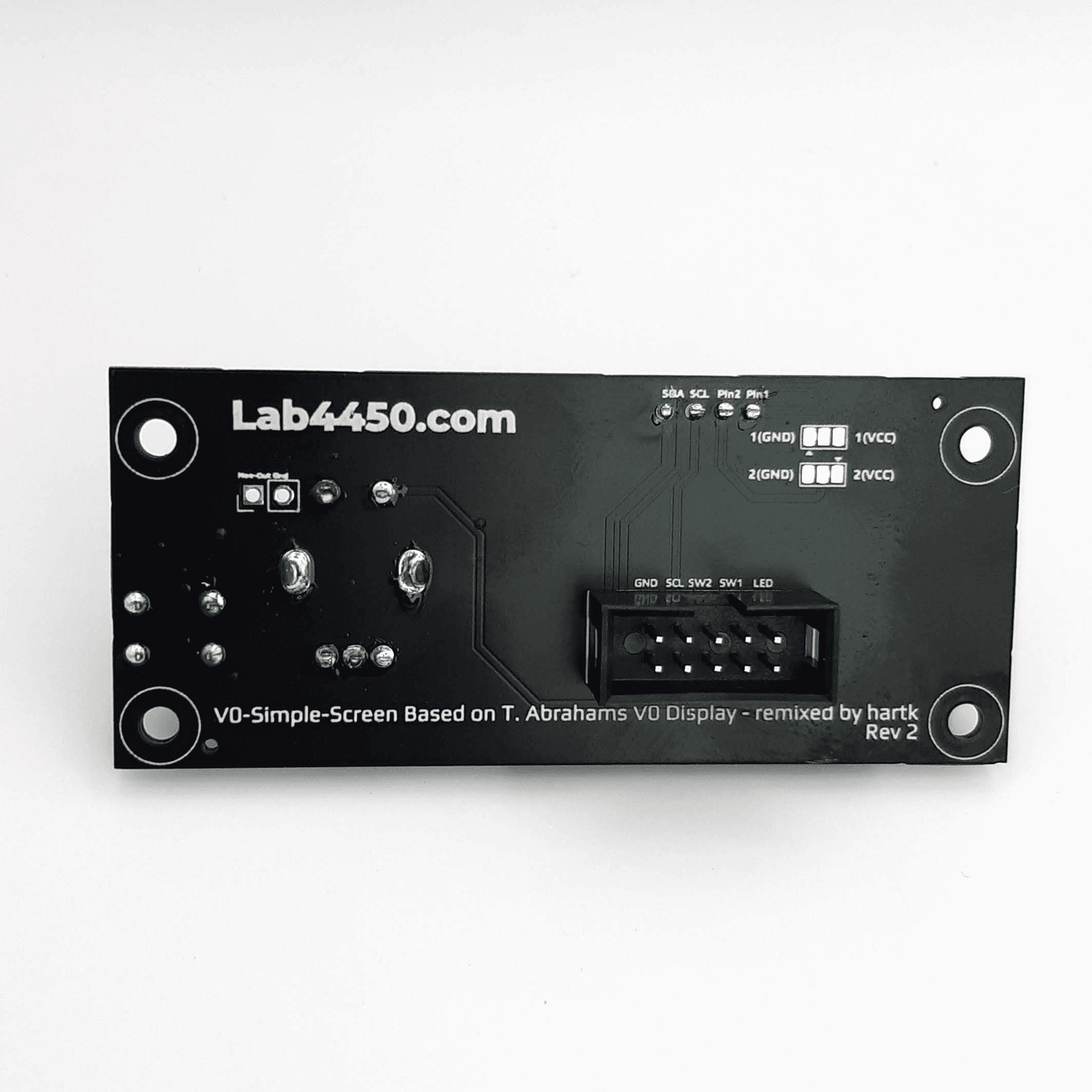
Designed and open-sourced by Hartk, the Voron V0 simple display uses a single ribbon cable to connect the display to the skr mini e3 v2 board. You don’t need anything else. No USB cables, no breakout boards, nothing! It’s plug and play.
Our display has the RGB Led included that can be configured to light up different colors according to different actions and status. Encoder rotates and clicks to allow navigation through the menu. Reset button on the right.
Recommend for voron v0.1 with SKR Mini. This product won’t work with SKR Pico.
This item is fully soldered and in ready condition to be used.
Includes 50cm 10pin ribbon cable.
We suggest printing these printed parts edited by us to fit this product properly instead of the original. Please super glue the spacer.stl between the bottom of the display and the PCB
We have two options available for sale:
- Voron v0 Hartk Simples display rev2
- Voron v0 Hartk Simples display rev2 + printed parts + fully mounted and assembled
For SKR mini E3 v1.2 please use this klipper config:
[display]
lcd_type: sh1106
click_pin: ^!PB6
i2c_bus: i2c1a
i2c_mcu = mcu
encoder_pins: ^PA9, ^PA10
kill_pin: ^!PB7
vcomh: 60
x_offset: 2

[neopixel display_led]
pin: PB5
color_order: GRB
initial_RED: 0.5
initial_GREEN: 0.5
initial_BLUE: 0.5
For SKR mini E3 v2 please use this klipper config:
[display]
lcd_type: sh1106
click_pin: ^!PA15
i2c_bus: i2c1a
i2c_mcu = mcu
encoder_pins: ^PA9, ^PA10
kill_pin: ^!PB15
vcomh: 60
x_offset: 2

[neopixel display_led]
pin: PB5
color_order: GRB
initial_RED: 0.5
initial_GREEN: 0.5
initial_BLUE: 0.5
For SKR mini E3 v3 please use this klipper config:
[display]
lcd_type: sh1106
click_pin: ^!PA15
i2c_bus: i2c1_PB8_PB9
i2c_mcu: mcu
encoder_pins: ^PA9,^PA10
kill_pin: ^!PD6
vcomh: 60
x_offset: 2

[neopixel display_led]
pin: PB5
color_order: GRB
initial_RED: 0.5
initial_GREEN: 0.5
initial_BLUE: 0.5

#sda = pb9
#scl = pb8
Example how to change to red color:
SET_LED LED=display_led RED=1.0 GREEN=0.0 BLUE=0.0 INDEX=1 TRANSMIT=1 SYNC=1
If your display is VCC GND SCL SDA and your display is getting too hot, its becaused vin and ground is switched and you need to cut trace and solder the pads on the back of the PCB. Cut the trace in green color and solder the two other pads in red color. Make a continuity test before connecting it to the mother board.

Author and info: https://github.com/hartk1213/MISC/tree/main/PCBs/v0_simple_display